Darcy Friction Factor Chart
Chart Tracking Trumps Knowledge and Intent in Efforts to Overturn the Election. For a flowing liquid water in general through a pipe the horizontal forces on water between two sections 1 and 2 are.
Pipe Friction Models Pump Flow
The friction factor for laminar flow is independent of roughness of the pipes inner surface.
. By Shane Darcy March. The friction factor for fluid flow can be determined using a Moody chart. These were all in 25mm galvanised.
The Darcy friction factor is a dimensionless quantity used in the DarcyWeisbach equation for the description of frictional losses in pipe or duct as well as for open-channel flowThis is also called the DarcyWeisbach friction factor resistance coefficient or simply friction factor. Cybersecurity-Related Actions Against Russia by Kirsten Eichensehr K_Eichensehr. The Darcy friction factor resistance coefficient is a dimensionless similarity parameter to describe the pressure loss in straight pipe sections.
P1 A P2 A FR P1 Pressure intensity at 1. Hydraulic conductivity symbolically represented as K unit. By defining the friction factor as a similarity parameter the friction factor can be determined in a reduced model scale of the later pipe system.
12 x 7 Rectangular 1000 cfm Solution. This can then be applied to the real scale and. Formula for calculating the loss of head due to friction is Darcys one.
It is convenient to calculate pressures in ducts using as a base an atmospheric pressure of zero. The Darcy-Weisbach equation is used to calculate the major pressure loss or head loss in a pipe duct or tube as a function of the pipes length and diameter the fluids density and mean velocity and an empirical value called the Darcy friction factor. Darcys formula for friction loss of head.
123 CALCULATE the head loss in a fluid system due to frictional losses using Darcys equation. The Darcy-Weisbach equation for calculating the friction loss in a pipe uses a dimensionless value known as the friction factor also known as the Darcy-Weisbach friction factor or the Moody friction factor and it is four times larger than the Fanning friction factor. FR Frictional Resistance at 2.
You will use this to determine the Darcy friction factor and in turn use the friction factor to determine the relative roughness of the pipe kD. From Table A-2 the Equivalent Round Size is 99 inches. The Moody Chart encouraged the use of the Darcy-Weisbach friction factor and this.
The equation is valid for both laminar flow and turbulent flow. Darcys equation can be used to calculate major losses. Pressure Losses Friction Equivalent Duct Sizes for Same Friction Loss From.
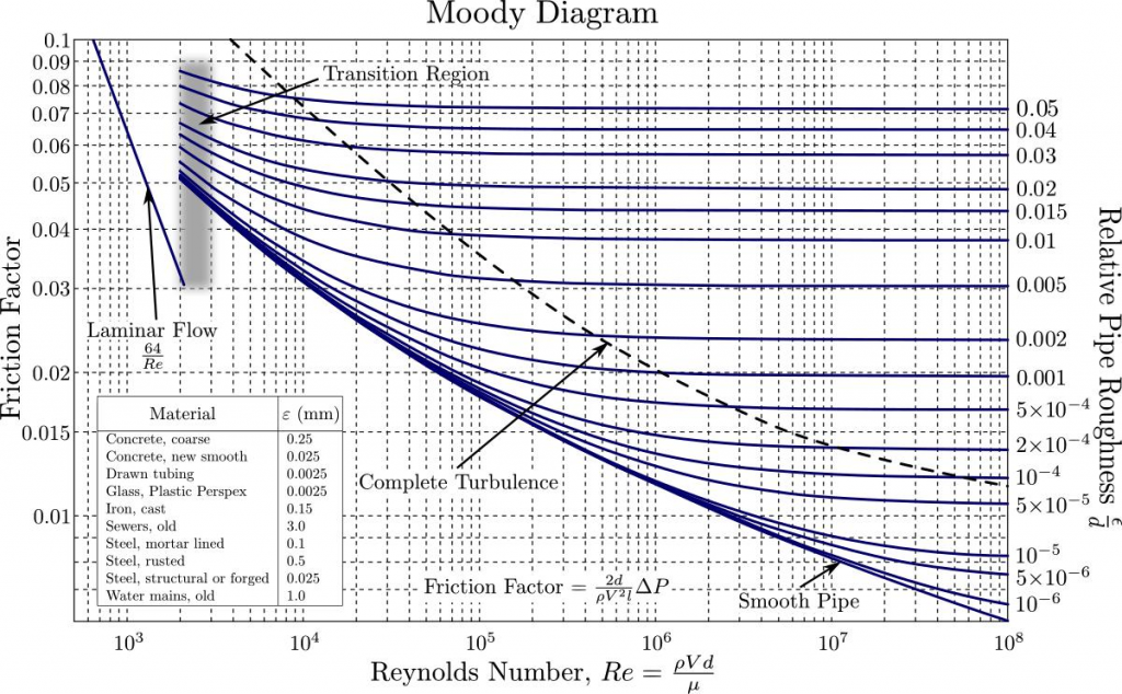
The Existential Threat of AI-Enhanced Disinformation Operations. Now known as The Moody Chart or sometimes the Friction Factor Chart enables a user to plot the Reynolds number and the Relative Roughness of the pipe and to establish a reasonably accurate value of the friction factor for turbulent flow conditions. P2 Pressure intensity at 2.
Use the friction chart at 1000 cfm in 99 inch Diameter to friction loss is 04 in water100 ft. The friction factor or Moody chart is. Total Pressure Velocity Pressure and Static Pressure.
Ms is a property of porous materials soils and rocks that describes the ease with which a fluid usually water can move through the pore space or fractures networkIt depends on the intrinsic permeability k unit. Friction Framing US. By Ryan Goodman Justin Hendrix and Clara Apt.
The Darcy-Weisbach Equation should be used for non-standard duct type such as flex duct. For the minor losses a single flow rate was passed through the pipe and the pressure was measured upstream and downstream of several typical objects two valves and an elbow bend. Darcy-Weisbach Equation for Calculating Pressure Losses Read More.
The friction factor for turbulent flow depends strongly on the relative roughness. Friction Factor Chart Moody Chart. In order for the Excel Goal Seek tool to work we need to enter an initial guess value for the friction factor.
Where is the Darcy friction factor from the above equation or the Moody Chart is the sublayer thickness is the pipe diameter is the density is the friction velocity not an actual velocity of the fluid is the average velocity of the plug in the pipe is the shear on the wall and is the pressure loss down the length of the pipe. A Cross sectional area of pipe. Mostly positive pressures occur in supply ducts and.
124 CALCULATE the equivalent length of pipe that would cause the same head loss as the minor losses that occur in individual components. 122 DETERMINE friction factors for various flow situations using the Moody chart. M 2 of the material the degree of saturation and on the density and viscosity of the fluid.
Typo Circulation should be Circular Example. Any small positive value should work. Friction Chart ASHRAE HANDBOOK 1997 13.
In the Outputs section of the spreadsheet we will create rows for the friction factor left and right sides of the Colebrook equation and an Objective. The friction factor has been determined to depend on the Reynolds number for.

Pin On Hhjj
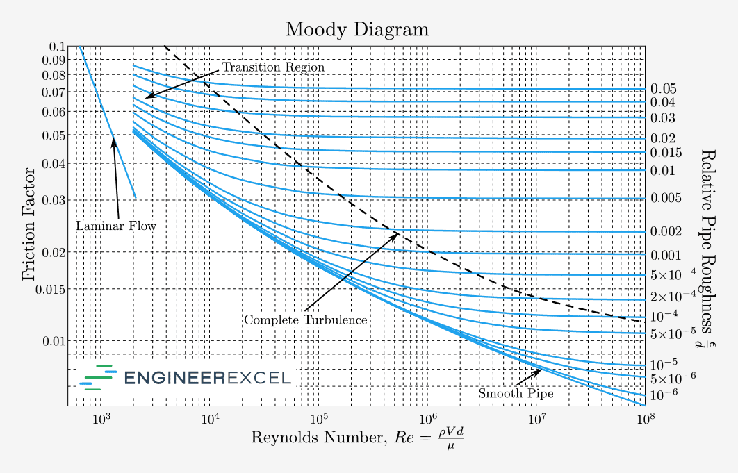
Moody Chart Calculator Engineerexcel

Moody Chart For Darcy Friction Factor Estimate Source Moody 1944 Download Scientific Diagram
Pipe Friction Factor Calculation
No comments for "Darcy Friction Factor Chart"
Post a Comment